The Six Subsystems of a Structured Cabling
This information is based on two standards: ANSI/TIA-568-C.0 (Generic Telecommunications Cabling for Customer Premises), which is used for generic infrastructures, and ANSI/TIA-568-C.1 (Commercial Building Telecommunications Cabling Standard), which is more commonly used with typical commercial building infrastructures.
1. Entrance Facilities (EF)
Entrance facilities contain the cables, network demarcation point(s), connecting hardware, protection devices and other equipment that connect to the access provider (AP) or private network cabling. It includes connections between outside plant and inside building cabling.
2. Equipment Room (ER)
The environmentally controlled centralized space for telecommunications equipment is usually more complex than a telecommunications room (TR) or telecommunications enclosure (TE). It usually houses the main cross-connect (MC) [Distributor C] and may also contain the intermediate cross-connects (ICs) [Distributor B], horizontal cross-connects (HCs) [Distributor A], or both.
3. Backbone Cabling
The backbone cabling provides interconnection between telecommunications rooms, equipment rooms, access provider (AP) spaces and entrance facilities. There are two subsystems defined for backbone cabling:
Cabling Subsystem 2 - Backbone cabling between the horizontal cross-connect (HC) [Distributor A (DA)] and the intermediate cross-connect (IC) [Distributor B (DB)]
Cabling Subsystem 3 – Backbone cabling between an intermediate cross-connect (IC) [Distributor B (DB)] and the main cross-connect (MC) [Distributor C (DC)] Recognized cabling
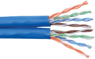
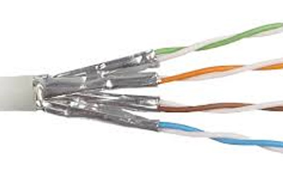
100-ohm twisted-pair cabling: Category 3, Category 5e, Category 6 or Category 6A
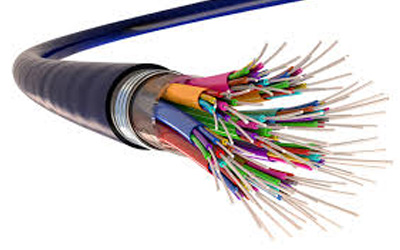
Multimode optical fiber cabling: 850 nm laser-optimized 50/125 μm is recommended; 62.5/125 μm and 50/125 μm is allowed
Single-mode optical fiber cabling
Telecommunications Room (TR) and Telecommunications Enclosure (TE)
A TR or TE houses the terminations of horizontal and backbone cables to connecting hardware including any jumpers or patch cords. It may also contain the IC or MC for different portions of the backbone cabling system. The TR or TE also provides a controlled environment to house telecommunications equipment, connecting hardware and splice closures serving a portion of the building.
The use of a telecommunications enclosure (TE) is for a specific implementation and not a general case. It is intended to serve a smaller floor area than a TR and may be used in addition to the minimum "one TR per floor" rule.
5. Horizontal Cabling – (Cabling Subsystem 1)
The horizontal cabling system extends from the work area’s telecommunications information outlet to the telecommunications room (TR) or telecommunications enclosure (TE). It includes horizontal cable, mechanical terminations, jumpers and patch cords located in the TR or TE and may incorporate multiuser telecommunications outlet assemblies (MUTOAs) and consolidation points (CPs). The maximum horizontal cable length shall be 90 m (295 ft.), independent of media type. If a MUTOA is deployed, the maximum horizontal balanced twisted-pair copper cable length shall be reduced.
6. Work Area
Work area (WA) components extend from the telecommunications outlet/connector end of the horizontal cabling system to the WA equipment.
A minimum of two telecommunications outlets (permanent links) should be provided for each work area. Multiuser telecommunications outlet assemblies (MUTOAs), if used, are part of the WA.
We have the knowledge, capacity and expertise to design, consult, supply, install and maintain all types of networks.
Contact Us
Got a question ? Feedback?
Send your message in the form below and we will get back to you as early as possible.
